
I actually expected some discrepancies near the border of the grid anyways. Green is for point chargesīy my eye the red fit is much better, at least in the interior. Blue is this calculation, Red is the best fit for infinite lines of charge. Potential along line between the connection points. The opacity of the arrows is the strength of the current. The arrows are the direction of current at each point (really a vector of both currentdown and currentright). The thick black lines are equipotentials. Here’s a plot that has a lot of information. I also had to name the current through the battery as an unknown.Īll together I have 2642 equations and 2641 unknowns.

I had to do some careful work around the edges, and I had to set one location to the voltage of the power supply (I used 1 Volt) and another to zero.
CONDUCTIVE PAPER FIELDLINES PRO
Ultimately I settled on a 30×30 grid as a compromise between good resolution and speed of calculation (everything below takes ~3 seconds to run on my Surface Pro 2). The red arrow indicated the guessed direction of the current. Sample of the resistor grid model under consideration.

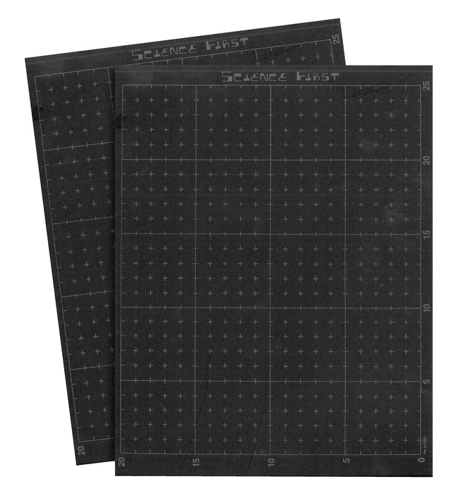
So I decided to look into what it would take to model the paper as a grid of resistors. Unfortunately I’ve only had success doing that sort of thing for very symmetric situations like a cone-shaped resistor (a popular homework problem that has problems of its own). I first did some thinking about doing this while considering the paper to be a continuous resistor. I wanted to see how good that analogy was, so I set out to calculate the current flow through the paper. I find it hard to get students to understand that, mostly because they can see that it really doesn’t have infinite lines of charge sticking out of it. Second the best analogy is with infinite lines of charge, instead of point charges. Instead it’s a very complex circuit with current flowing in all kinds of weird ways. We don’t have charged locations on the paper, so saying that it’s measuring potentials and fields is not correct. First, it’s not an electrostatic situation. In principle this is a cool lab (and not as sadistic as the ones that electrify goldfish bowls trying to get the fish to line up on equipotentials to minimize the pain). The strength of the field comes from the density of the equipotentials. We ask students to find equipotentials on the paper and then to plot what the electric field must look like by plotting vectors at all times perpendicular to the equipotentials. At my school we have a lab for electric fields/potentials where they measure potentials at different locations on a piece of conducting paper that has been attached to a power supply (the + lead and – lead of the power supply are placed at different points and the voltmeter + lead is anywhere on the paper and – lead is connected to the – lead of the power supply).


 0 kommentar(er)
